
A few years ago I bought a KV amplifier. Inoperative, but I preferred the repair to building from scratch and finding the necessary parts. This amplifier was wired according to G2DAF, which is also usually referred to as connection with a passive grid.
You will read:
What is the advantage of the G2DAF amplifier?
The G2DAF amplifier creates the voltage for the g2 grid by rectifying part of the drive signal. I.e, that the stabilizer Ug2 is not necessary and the quiescent current of the tube without excitation is zero. This has a positive effect on efficiency, possibility to use higher anode voltage and slightly higher efficiency.
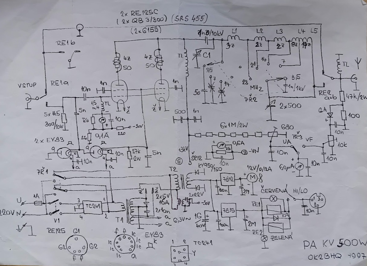
The disadvantage is, that the amplifier needs a slightly higher drive level, appropriate solution of the input circuit and monitoring of DC parameters in operation, so that the signal is processed with as little distortion as possible.
Anode choke
The original choke was destroyed. Either by operation outside its load or in its resonance area. However, the body was only minimally damaged, so I removed the remains of the wire, cleaned the body and wound it with new CuL wire. It required patience, because there are threads 300 divided into sections after 165, 65, 35, 20 and 15 threads.

The separating HV capacitor was just blown away by the smoke from the choke. It was enough to clean it. This was followed by a test with a nanoVNA to verify the output pi-cell and the self-resonances of the anode choke.
Procedure for checking the output pi-cell and the self-resonances of the anode choke
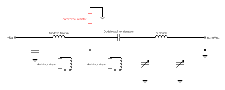
- disconnect the power supply Ua from the amplifier (extremely important!)
- then we load the tube anodes with the assumed resistance of the anode circuit
- we heat up the amplifier and switch to broadcasting
- the resonance frequencies of the anode choke can be measured more easily when the amplifier is switched to band 28 MHz with both rotary capacitors set to almost minimum capacity
- the resonant frequencies of the anode choke will be seen on the nanoVNA screen. These can be overlooked with a smaller number of nanoVNA measurement steps. It is then appropriate to measure in several ranges, for example 1 up to 10MHz, 10 to 20 MHz, 20 to 35 MHz
- I registered the resonance of the anode choke up to around 34 MHz. However, if the resonance falls in the amateur radio band or in its close vicinity, the amplifier cannot be tuned on this band, possibly splashes, or the anode choke burns. Such a choke is not suitable and must be rewound
- if the anode choke is OK, we proceed to check the pi-element. We tune to PSV 1,0 in every radio amateur band. If such PSV cannot be achieved, pi-cell requires modification
- for me it required soldering back the parallel capacitor (one outlet was disconnected) and change the turn in the 80m zone. Without it, the pi-cell could not be tuned to this band, its resonance was higher. The other bands were correct.
- at the end, do not forget to disconnect the resistance from the tube anodes and reconnect the Ua input
Income problems
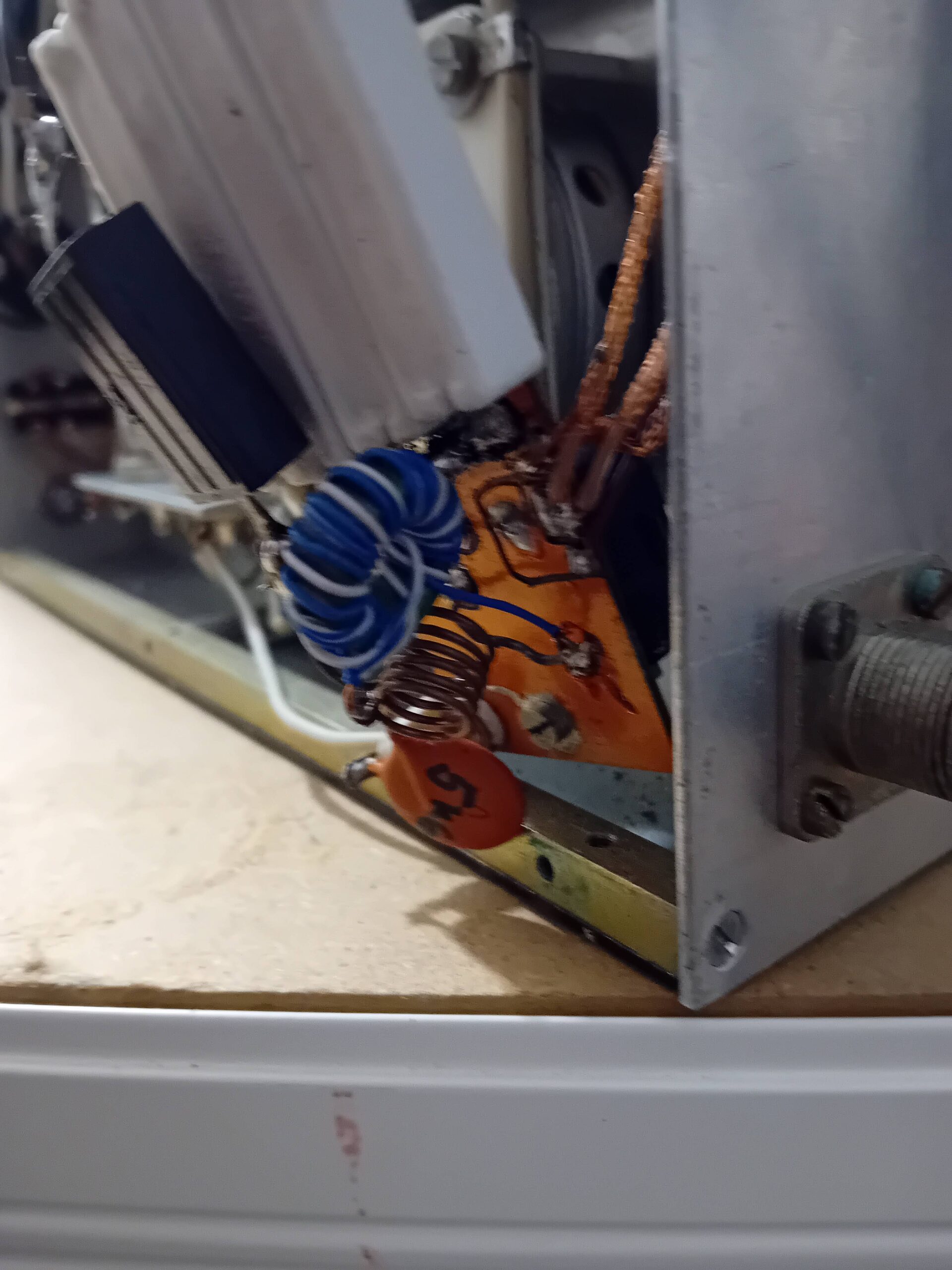
The original owner reported problems with the reception relay. However, he did not want to change the relay in a very inaccessible place. Since I also registered the occasional loss of income, I started searching with an ohmmeter. It was pleasant, that the problem is not caused by the relay, but connecting coaxial cable between input and output relay. Replace 25 centimeters of coaxial cable was much easier.
Tube test QY3-125
I had no experience with QY3-125 tubes before. Visually, they didn't look very good, but he decided to give them a chance. First I am them 24 hours with moderate blowing. Then came the critical test: anode voltage connection. The tubes lasted him. Since this connection does not release quiescent current through them, so it came to the next test.
Putting the amplifier into operation
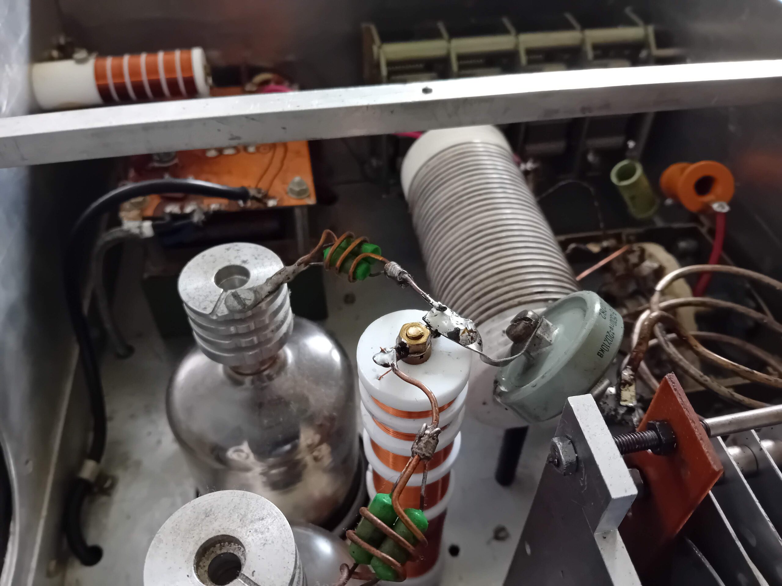
So I had to start waking up the amplifier. It was confirmed, that the pre-tuning with the nanoVNA was correct. The amplifier immediately transmitted power on all bands. However, for identical output power, the excitation on each band was quite different. The measurement showed, that the cause will be a high input PSV. But 28 MHz was PSV up to 2,5:1. A look at the load resistors suggests why:

The designer used power resistors with a large inductance. I tried to replace them with a resistor of the same value in a miniature non-inductive design and measured it using an antenna analyzer. With such a resistor PSV dropped below 1,5 and reached the ideal value on several bands.
So what to replace unsuitable resistors with. Searching the Internet, I found a suitable resistance resistor with the designation RPT100. These resistors are designated as non-inductive, exactly like that, what I needed. But reality showed, that such a resistor is not inductive. Fortunately, I got my hands on several Alcatel 100-ohm non-inductive resistors 39-4696, so I assembled a suitable resistor from the trio. Although this method is not ideal, but it is enough for KV. The entrance PSV has thus significantly improved. The amplifier thus gives a power of 500W on most bands.
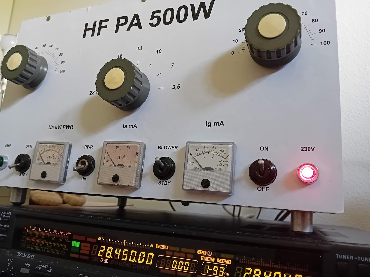
Cabinet for amplifier and aesthetic improvement
Since the amplifier must be visible, so it also depends on the visual design. Some of the original owners drilled two rows of holes in the top panel. However, very unsightly, different shapes and displacements. After consideration, I decided not to change the panel. In Corel Draw I designed the lines and hole sizes like this, to hide these inaccuracies as much as possible after drilling. I printed the resulting template on a self-adhesive label. She then presented a guide on how to grind the holes.

The amplifier also received a new color. I sanded off the original color. This was followed by spraying with the base color and then black. The top layer is additionally covered with a colorless spray paint.
The second question was about the front panel. The size is larger than A4, which I can print on a self-adhesive label. I've been toying with the idea of a custom aluminum faceplate through https://www.quickpanel.sk However, the price is not negligible. So I drew a new front panel in Corel Draw. The inspiration comes from the solutions of other amplifiers. The drawing of the front panel is printed on two self-adhesive labels. After gluing, the edges were carefully trimmed and three times very lightly sprayed with colorless varnish. This method will ensure, so that the panel is also resistant to abrasion and dirt. Spray very lightly, because the label tends to curl after being soaked.

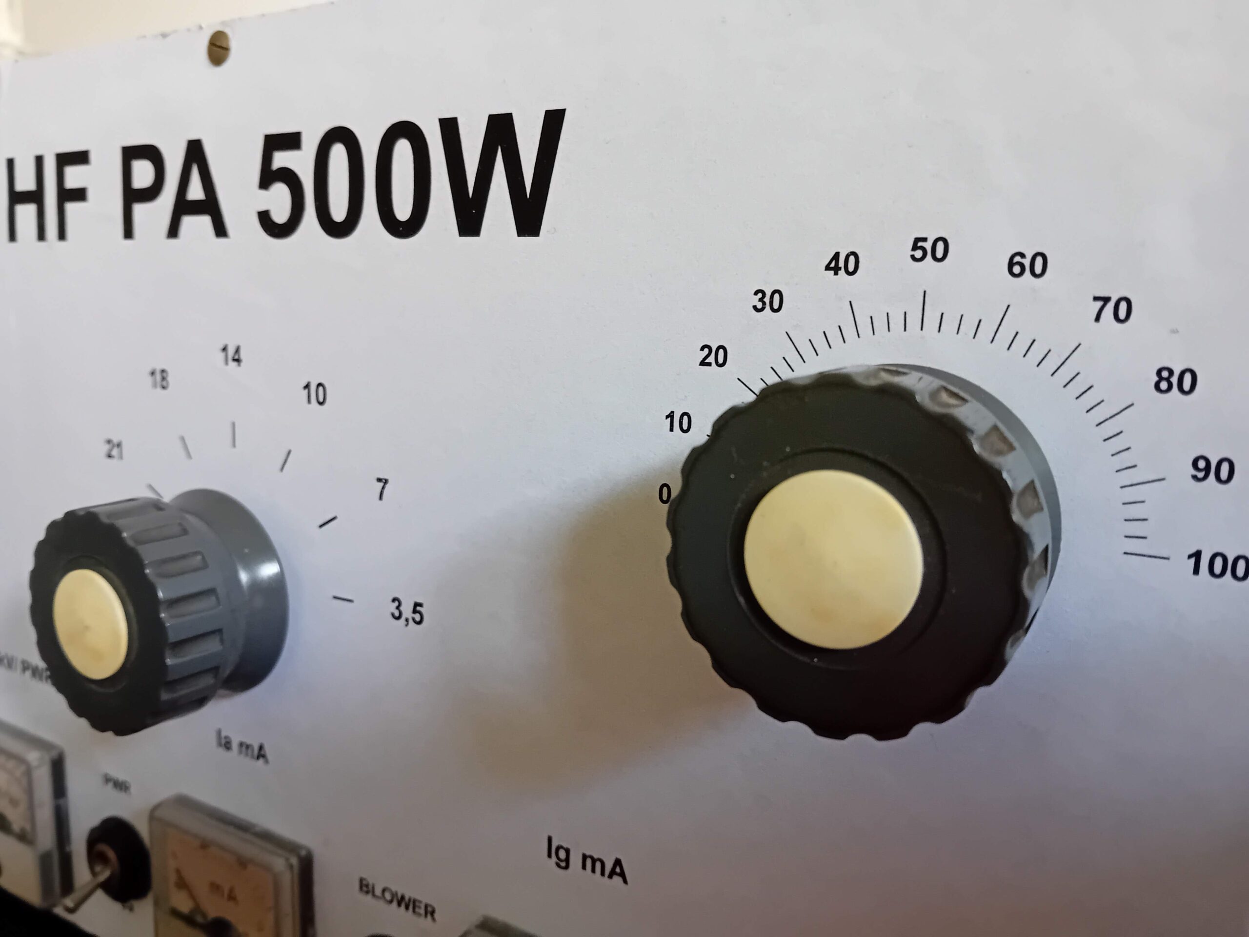
The tuning capacitors and the switch in the pi-cell got new instrument knobs. I had in stock TESLA WF series instrument knobs with a diameter 40 millimeters, which came in very handy. These vintage knobs are very well made and outperform most modern instrument knobs, which can be purchased.
Diameter washers came between the knob and the front panel 25 millimeters. They are cut from the rest of an old foam mat. Pressing them between the knob and the front panel creates a frictional force, which is more accurate for debugging convenience. At the same time, they fill the gap between the knob and the front panel.
Originally, the amplifier had two indicator lamps in a red and green holder on the front panel. One bulb was missing, the other lit up occasionally. I soldered LEDs with a diameter to the holders 5 millimeters and added a limiting resistor so, so that the LED current is approx 15 miliampérov.
G2DAF amplifier in practice
Classic amplifiers are characterized by a significant effort to stabilize the Ug1 and Ug2 voltages. The quality of this stabilization is strongly influenced by the spectral purity and linearity of the amplifier. I was therefore curious as to how the amplifier would behave in practice, whose Ug2 changes depending on the excitation signal. I made a comparison using an SDR receiver with the amplifier off and on. Perhaps surprisingly, but no intermodulation products were seen on the spectrum after switching on the amplifier, just a significantly stronger signal. In the future, I am also planning to take the two-tone SSB exam.
If you could get your hands on a G2DAF amplifier, so I recommend studying "Linear power amplifier G2DAF - history, theory and practice" https://www.radiozurnal.sk/radioamater/download/cisla/2000-6.pdf and https://www.radiozurnal.sk/radioamater/download/cisla/2001-1.pdf
The material contains a lot of knowledge and advice, how to implement such an amplifier and what are its properties. However, with tube amplifiers, you have to keep this in mind, that one is working with life-threatening voltages! If you want to be sure of safety, rather reach for amplifiers with LDMOS, which work with safer voltages.


