The uBITX pro transceiver kits were characterized by poor intermodulation properties during transmission in lower versions. I.e, that the transmitted signal would take up much more bandwidth in the band than allowed and could cause interference to ambient frequencies. Intermodulation products are measured two-tone test. The article describes the adjustment, which will significantly improve the quality of the transmitted signal.
You will read:
Two-tone test of SSB transmitter
Warren WA8TOD made very detailed measurements by two-tone SSB test. The two-tone test is based on the principle, that two low frequency modulation signals are fed to the SSB transmitter, for example 700 Hz a 1900 Hz. New signals are generated on the nonlinearities of the transmitter, which we call intermodulation products. In practice, IMD products are most often measured 3. and 5th Order. Based on their curve, the generation of IMD products of higher orders can then be estimated.
What is the source of IMD products in uBITX?
WA8TOD found out, that The main source of IMD products are bi-detection amplifiers. From the point of view of simplification of the construction, the original connection is modified, which manifests itself in greater frequency dependence, but especially worse IMD properties.
The second reason is the properties of mixers and active elements. In principle, they create other IMD products and affect the individual parts of the transmitter.
Ways to improve IMD products in uBITX
This has led several designers, who made a series of adjustments. Newer versions of the uBITX transceiver already have some improvements directly incorporated. In particular, the frequencies in uBITX have changed, transistors in amplifiers, adjusting the operating point of the amplifier and adding an LC filter after the second bi-directional amplifier.
Warren tried changing bi-directional amplifiers to simple ones amplifiers with MMIC. He achieved a significant improvement in IMD products. However, even within this broader generated spectrum, this adjustment does not completely address the purity of the transmitted signal within the shortwave spectrum.. Therefore, it is expedient to use either an additive filter 45 MHz (version 3) or LC filter.
IMD modification and measurement of IMD products uBITX
First, I performed an improvised measurement of the IMD of uBITX products. I used an online two-tone signal generator from the site http://www.onlinetonegenerator.com/binauralbeats.html The first signal had a sinusoidal course on the frequency 700 Hz. Second the same waveform on the frequency 1900 Hz. The spacing of these signals was therefore 1200 Hz or in other words 1,2 kHz.
This signal was fed to a transceiver switched to SSB transmission. Behind the bi-directional amplifier at the frequency limit 45 The MHz divider has been included 1200 / 50 ohms through a 1nF capacitor. He was pinned to this point cheap SDR receiver with RTL2832. As software was used SDR Console. It is a temporary and indicative measurement, but it can help a lot.
IMD measurements of uBITX products
First, the products were measured unmodified amplifier and output power was set with the wattmeter to 2W:

On frequencies 44 991,8 kHz a 44 993 kHz shows both modulation signals. To, that the frequency is a few kHz lower is probably due to the SDR frequency deviation. See both tips on either side, of which we are most interested in those on 44 994,2 kHz (teda o 1,2 kHz higher than the upper frequency. It is IMD 3rd series and as long as we believe the indication, is len -12dB below the level of modulation signals. The 1,2 kHz higher again (44 995,4 kHz) is located IMD 5th order. Ten you c.. -22 dB below the level of modulation signals.

He was subsequently included modified amplifier with filter. This amplifier has a slightly higher gain, so output power approached 3W. Here, a slightly different bandwidth is set during the measurement, but it can be observed immediately, that the resulting signal is clearer. IMD 3rd order are approx. -23 dB below the level of modulation signals and IMD 5th order approx. -33 dB below the level of modulation signals.
The last measurement was performed with amplifier filter, no modulation so, to output the power was again 2W:

IMD 3rd order are approx. -34 dB below the level of modulation signals and IMD 5th order approx. -41 dB below the level of modulation signals. This is already very clear signal on a simple transceiver and completely suitable for operation on amateur radio bands.
Modification in uBITX to improve IMD products
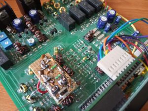
Original bi-directional amplifier with Q20 transistors, Q21 and Q22 have been discarded. Capacitors C20 and C22 were soldered from the printed circuit board. The amplifier was built on a piece of universal printed circuit board. Both stages are fitted MMIC MSA-1105 (domestic supplies). Gain these degrees could be c.. 2x 12dB.


They are followed by a transformer, whose task is to adjust the impedance of the output of the amplifiers (50 Ohm) in impedancii crystal filter 45MHz (ebay). This is estimated at 600 Ohm. Transformer ma 2 threads on the primary winding, 7 threads on the secondary winding. The output transformer is the same, which, however, is connected in reverse. This achieves the impedance again 50 Ohm. A two-hole BN core is used 43-2402 (is not a condition). The output is connected directly to the mixer (R27 is not used either).
Wiring diagram

The amplifier is mounted above the uBITX main PCB. In this way, relatively short connections are achieved.
Conclusion
With the described modification, it is possible to significantly improve the IMD of the uBITX transceiver. It would also be ideal to replace the first bi-directional frequency amplifier 12 MHz, which would further improve the quality of the output signal.
It is also presented method of measuring IMD products of SSB transmitters, which is available to a wide range of amateur radio as it does not use any unavailable technique.
Used sources
http://www.onlinetonegenerator.com/binauralbeats.html
https://ubitx.net/2018/09/15/details-of-the-anti-spurs-mod-added-45mhz-filter/
https://ubitx.net/2018/10/21/the-last-challenge-reducing-imd/
https://ubitx.net/2018/09/15/on-the-matter-of-ubitx-imd/
https://ubitx.net/2018/09/15/imd-using-an-alternative-mmic-amplifier/
https://www.sdr-radio.com/download
Update 30.05.2020 – change of the first amplifier to SNA586 MMIC
This significant shift in the quality of the transmitted signal is definitely worth using the MMIC instead of the Q40 amplifier – Q42. Due to the low frequency, another MMIC would be used, SNA586. Measurement results:

When performing 2W, 3rd order IMD products are suppressed by a fantastic -45dB!


If we increase the excitation, so IMD products will grow. This could be considered here, whether or not to adjust the excitation level of the transmitter with trimmer RV1. If IMD products are created in the first amplifiers, thus, by increasing the excitation of the undersized output stage, the quality of the output signal could be improved.
However, it can be said, that if we limit the output power to 3W and less, thus, it is possible to excite the output stage with such a transmitter without fear of it, that the signal would be poor.


