
How to achieve maximum gain of portable antennas at 144MHz? Unlike single yagi, which would have to have a long boom and considerable height above the ground, so the group OK2VZE, OK2LOL, OK1ZHS v Alpe Adria contest 2008 used system 4×6 elements yagi . That's it the antenna is also used by OK2R.
You will read:
Single yagi / antenna system
The longer the antenna, thus it must be placed higher above the ground. If we consider profit of about. 16dBi, so it is achieved by a single yagi antenna with a boom around 8 meters. This represents a greater moment of the required force for rotation and, of course, a higher mast.
Advantages of a single yagi antenna
clean radiation pattern
absence of antenna stacking
quick assembly of a split antenna
Disadvantages of single antennas
a narrow radiation pattern recognizable especially in the horizontal plane
higher mast required, at least 7 meters
demanding lifting and lowering of the mast with antenna
more torque required to rotate the antenna

Antenna system with a profit of approx. 16dBi can also be achieved by a system of two, because of, four or more antennas. A larger number of antennas is used as a fixed antenna system with a wide radiating lobe.
Advantages of a system of two antennas on top of each other
shorter antennas with a boom around are sufficient 3,5 meters
the radiation pattern in the horizontal plane is wider than in single yagi
the torque for rotating the antenna is lower
higher mast required, at least 7 meters
Disadvantages of a system of two antennas on top of each other
the need to stacking two antennas
demanding lifting and lowering of the mast with antennas


Advantages of a system of three or four antennas on top of each other
shorter antennas with a boom around are sufficient 2,2 meters, or. 1,5 meters (four antennas)
the radiation pattern in the horizontal plane is wider than in single yagi
Disadvantages of a system of three or four antennas on top of each other
higher mast required, at least 8 to 10 meters
demanding lifting and lowering of the mast with antenna
the need to combine three antennas
antennas with a length over 1,5 subways must have a split boom due to transportation inside the car
Advantages of a system of four antennas in configuration 2×2 (H-configuration)
shorter antennas with a boom around are sufficient 1,5 meters
such antennas can be transported inside a car
a lower mast with a height of about is sufficient 5 meters
easier mast lifting
acceptable torque for rotation
Disadvantages of a system of four antennas in configuration 2×2 (H-configuration)
use of H-construction
the need to combine four antennas
the horizontal plane radiation pattern is narrower and less clear than in other antenna or single yagi configurations

HINT – countersunk nuts
Petr OK1FIG used countersunk nuts in its construction, thus achieving the lower part of the boom antennas without larger protrusions. In addition to aesthetics, this has the advantage of not catching antennas when inserted into the car
Choice of antenna options
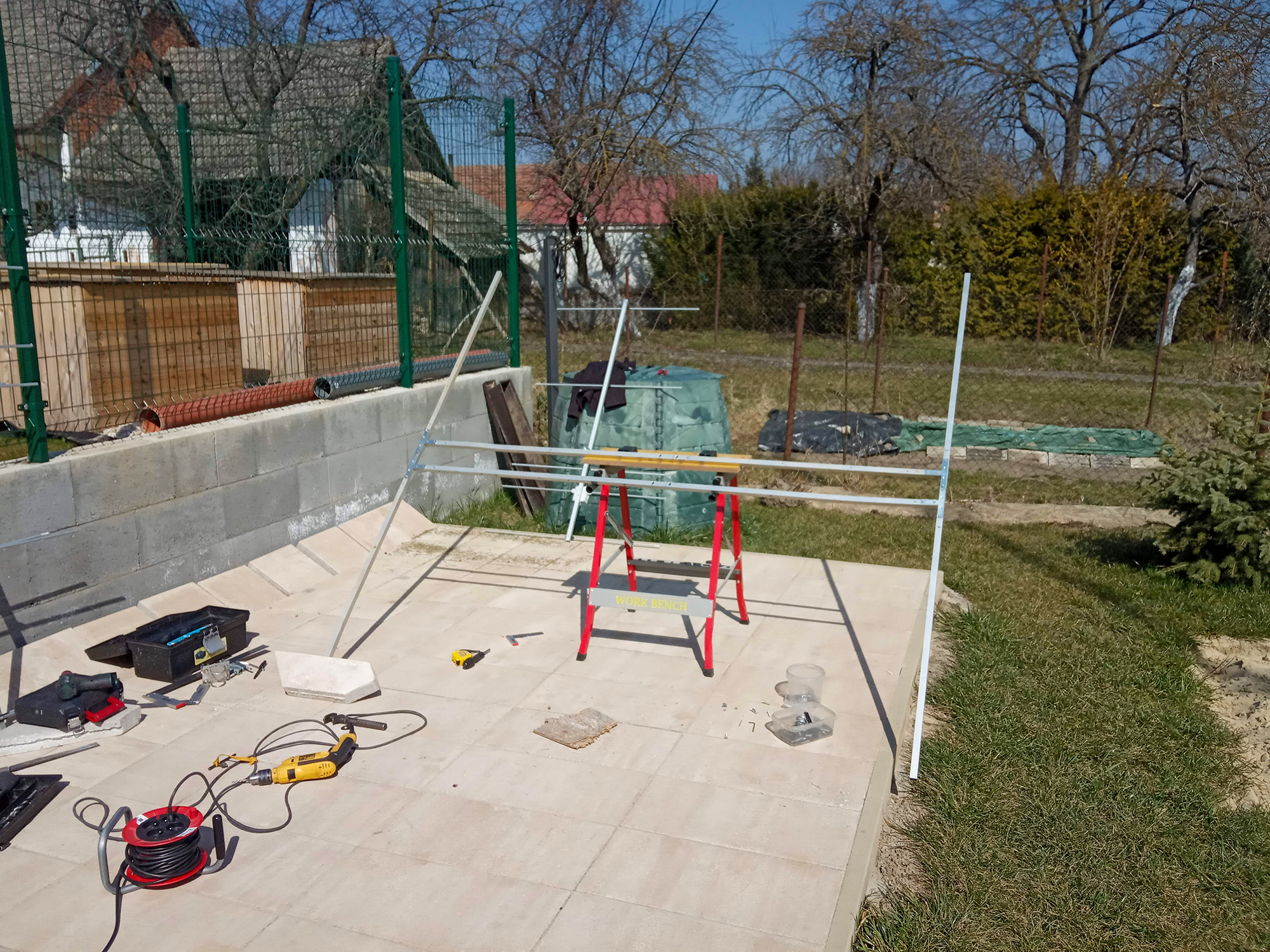
I build antennas in one person. Examples show how larger antennas can or cannot be lifted antenna lifting. However, sometimes the wind blows and the higher mast can be difficult to lift anyway. I preferred the construction of four shorter yagi antennas in configuration 2×2 (H-configuration) also because of that, that such antennas can be transported without disassembly inside a car.
YU7XL, S53WW, DG7YBN, G0KSC, DK7ZB yagi
Such short antennas are not described YU7EF, the shortest model is 6 elemental yagi. Design S53WW is interesting in terms of profit, but it requires a loop dipole which is more difficult to manufacture. The antenna is also more sensitive to the surrounding environment and the advantage of production.
The short oblong antennas of the YU7XL are interesting in terms of boom-to-gain ratio. However, the spatial design complicates the transport of the antennas as well as the assembly of the square.
Remaining DG7YBN designs, G0KSC, DK7ZB yagi antennas are at the individual preference of the radio amateur. I chose the design from DK7ZB. Antenna with length 1,5 subway has 5 elements and a profit of approx. 8,4 dBd. The impedance is 50 Ohm. Power is via so-called. coaxial cable balun.
HINT - use of square profiles
Using a profile 20 x 20 mm for the construction of the supporting H-tag and individual boom antennas, their connection will be simplified. This is possible with flat T-couplings with dimensions 120 mm x 54 mm x 19 mm (purchased in OBI)
HINT - use a cordless screwdriver
Assembly and disassembly of the H-piece and connection of antennas is accelerated by a cordless screwdriver. Stainless steel countersunk Allen screws are used 7991 M5x30 and standard stainless steel hexagon nut M5.
Fabrication 5 element antennas DK7ZB yagi
The production of antennas itself has been described many times. The elements are fastened to the boom in a black polypropylene holder using an M4 screw and countersunk nuts. They have an average 10 mm, boom is out of profile 20 x 20 mm.

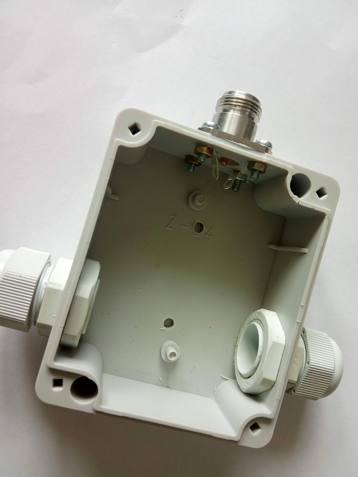
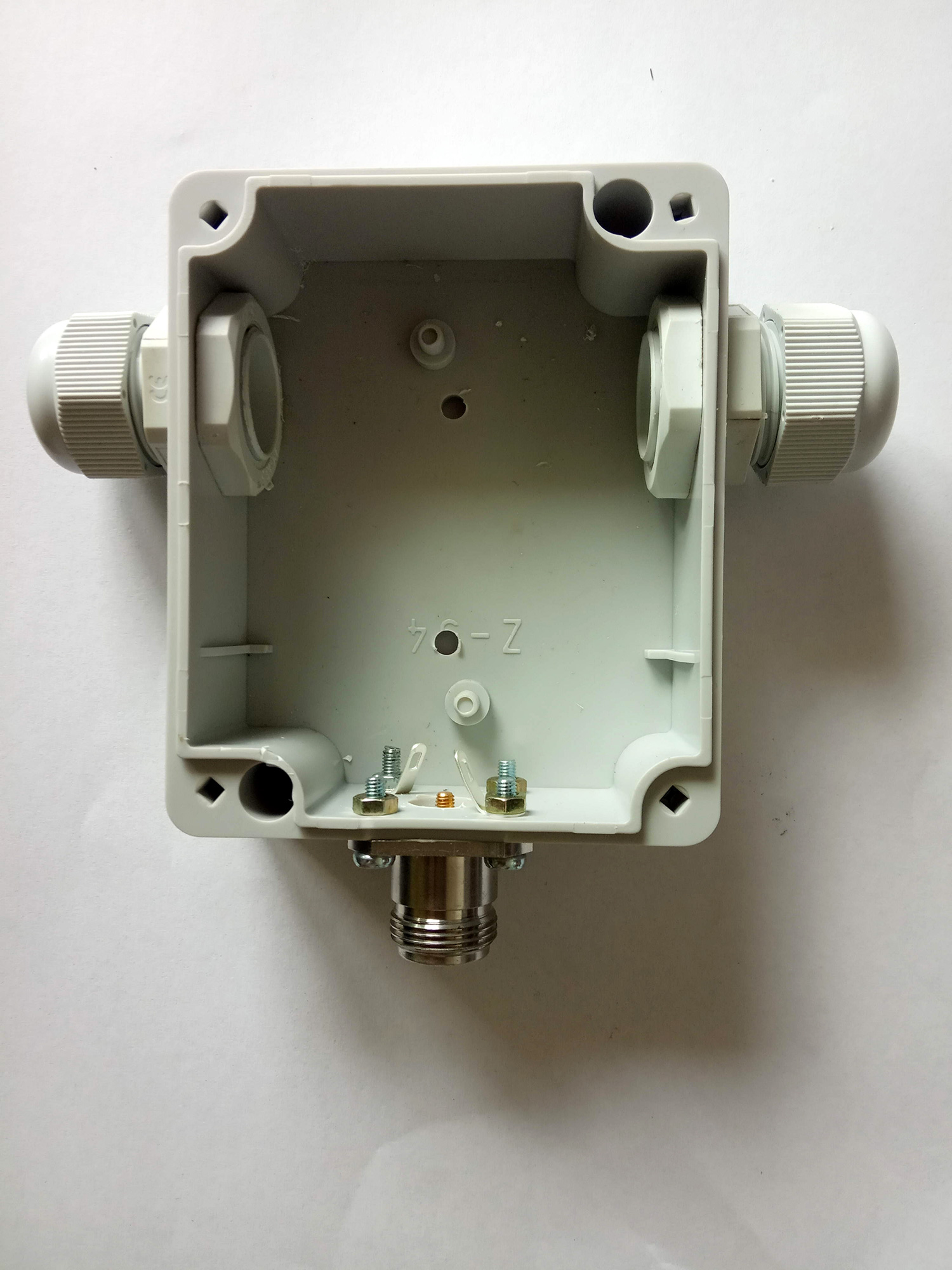
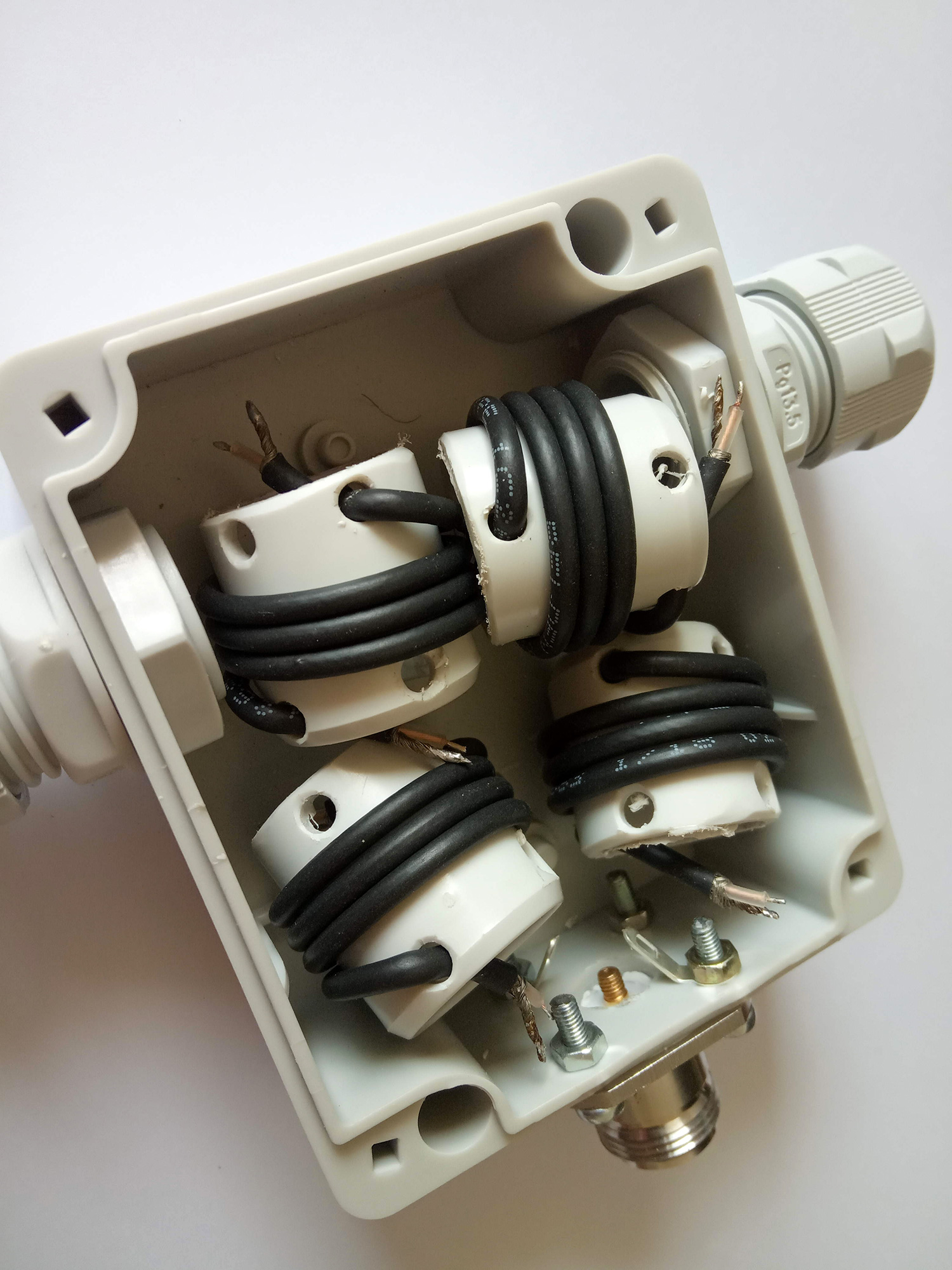
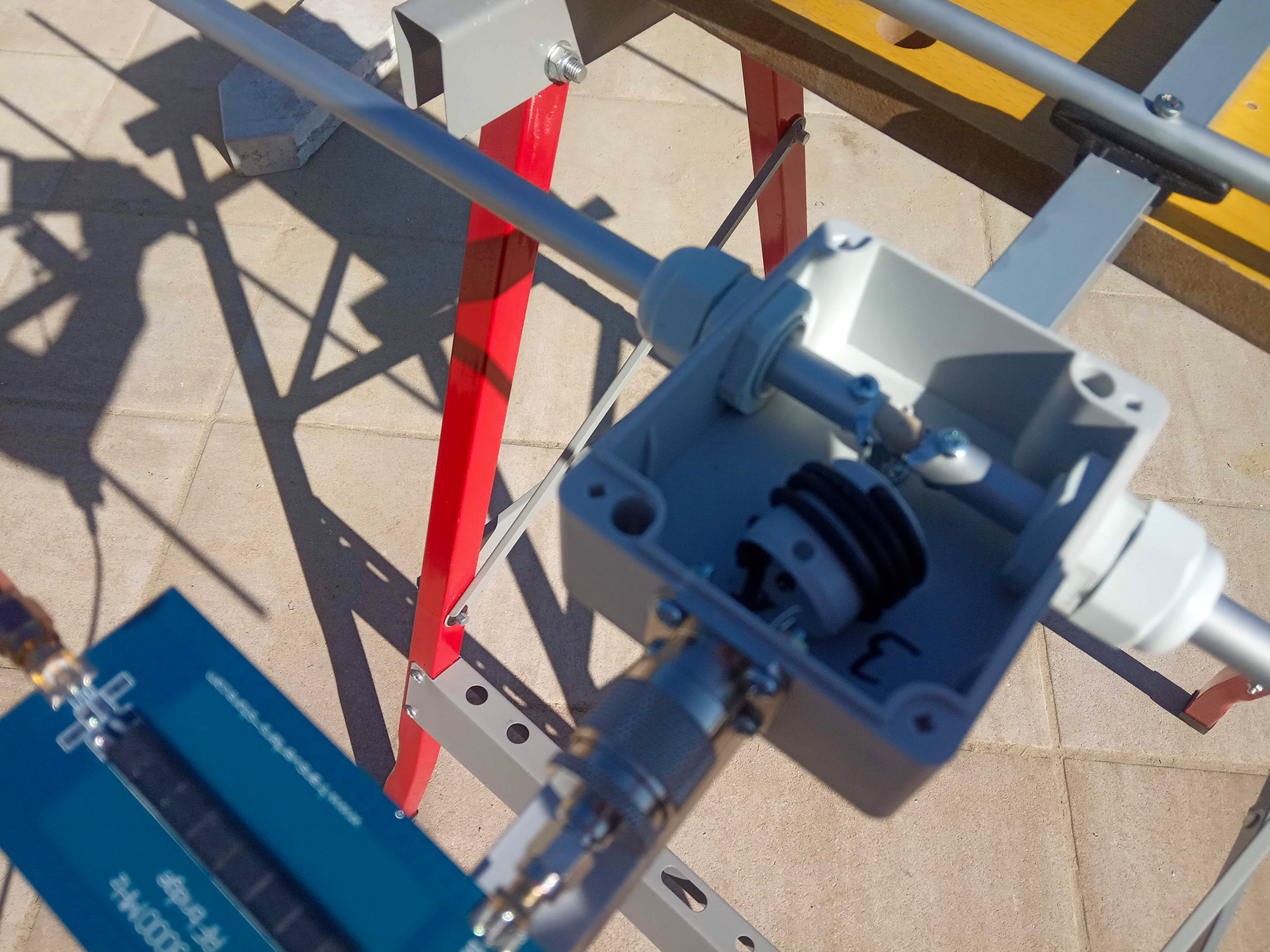
The radiator is mounted by cable glands in boxes Z54 = KP 45 (Z54J). It's inside choke balun made of Belden coaxial 8216 RG174 / U. Its length is 34,3 centimeters, which includes the coaxial cable shortening factor (0,66). The length is measured between the ends of the braid - the leads to the radiator and the connector do not count towards the length, but they should be as short as possible. An N-connector is used, which is connected to the boom.
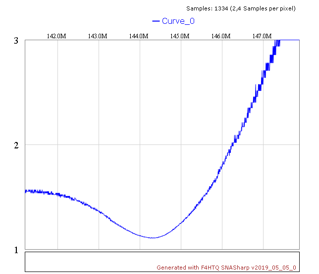
Measurement 5 element antennas DK7ZB yagi

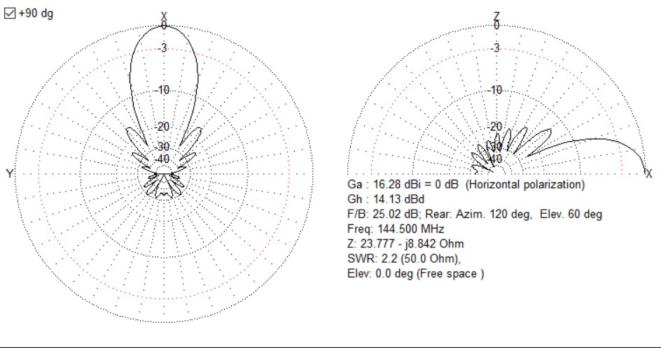
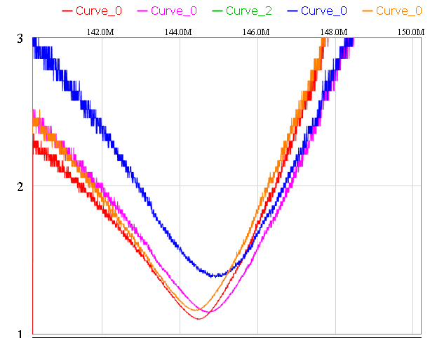
The antennas thus assembled were measured under temporary conditions with such a result
The third antenna was slightly tuned to a different shape of solder lugs connected to the radiator.
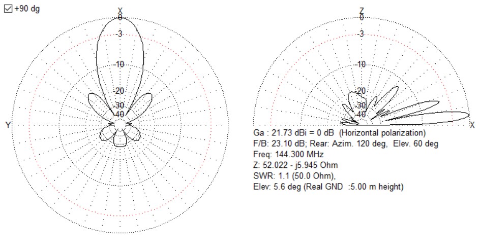
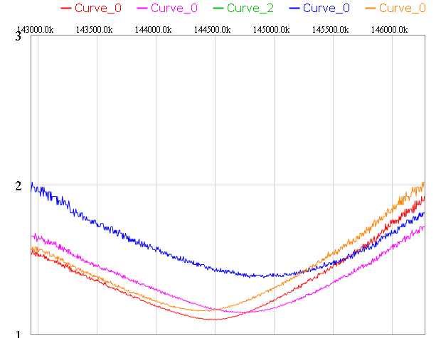
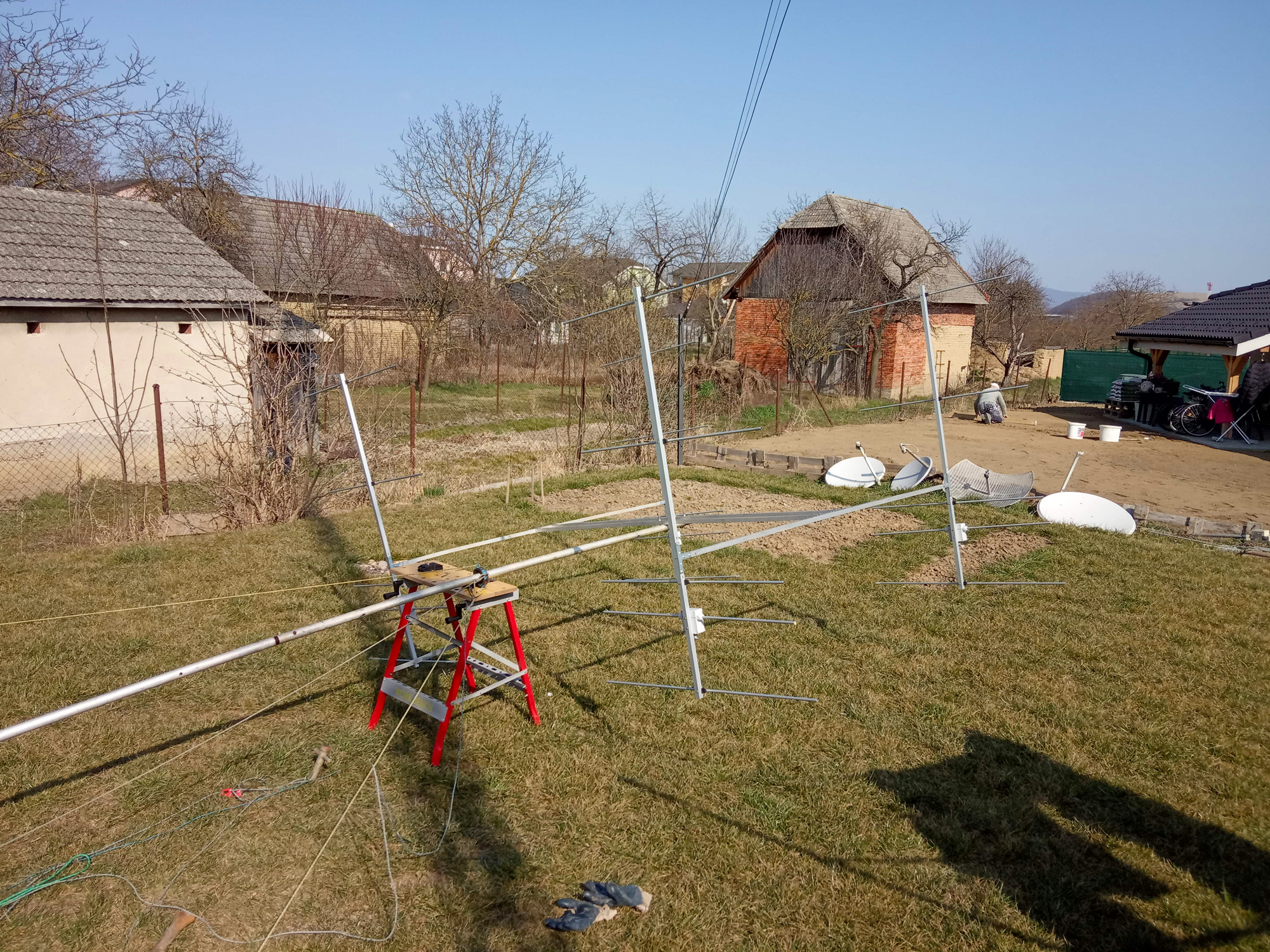
Measurement of assembled square DK7ZB yagi antennas 144MHz for portable on mast 5 m

Photographs from the fabrication of the DK7ZB yagi radiator box and choke baluns

HINT - filling the box with PUR foam
The idea comes from Vlad OK1VPZ. In addition to improving the flow resistance of the box, the radiator is also more firmly fixed.
H-configuration design for four yagi antennas
H-čko also uses it profile 20 x 20 mm and flat T couplings. They are also used to connect boom antennas. Here it is good to use an angle, so that the antennas are held exactly. Don't forget them Mark, otherwise it could happen, that you swap the individual antennas and the place in the phase will be in antiphase.
Two threaded loops are used to attach to the mast.
Price of a stacked DK7ZB yagi antenna 144MHz for portable
Indicative material budget
profile 20 x 20 mm in length 8 meters 80 €
tubes 10 mm in length 20 meters 30 €
element holders 16 €
T couplings 16 pieces 6 €
boxes Z54 12 €
N connectors 16 €
Belden coaxial cable 8216 RG174 / U 3 €
PUR foam worth 4 €
nuts, screws, soldering lugs 13 €
our antennas splitter 70 €
RF240 phasing cables with N connectors 40 €
TOTAL: 290€
I used the material for the construction, who had mostly at home, several prices are therefore only indicative for those interested in the implementation of a similar antenna.
Practical experience with stacked DK7ZB yagi antennas 144MHz
Assembly and disassembly of antennas in field conditions is very good. Lifting the mast in one person is not a big problem.

The antenna was practically compared with 8 element DK7ZB yagi, which has the declared profit 12 dBd. The system has a theoretical gain 14,2 dBd (without taking into account the losses in the phasing cables and the combiner).
In operation, it clearly outperformed the single yagi despite the handicap of power supply with a worse and longer coaxial cable. I also appreciated the more directional antenna when receiving as much 8 km away is OM3CQF, 12 km OM3Kii a 16 km OM2ALD.


