
R2CW is a VHF CW / SSB transceiver with excellent parameters. This predestines it as a contest device. The disadvantage of this transceiver is, that it does not have some of the conveniences of modern equipment. One is a visual overview of the signals. However, the SDR spectroscope solves this function. The connection and idea is in principle also suitable for other transceivers, not just for R2CW.
You will read:
R2CW intermediate frequency connection point
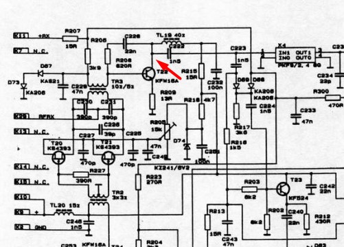
R2CW uses one intermediate frequency 9 MHz. It has an 8-crystal SSB filter. If we want to cover the signal spectrum, so we have to output the IF signal before this filter. A possible point is the KFW16A collector of transistor T22 on the mixer board (SMS) as shown in the diagram:
An isolating amplifier is connected to this point. Its job is to connect the SDR receiver so, to avoid signal interference or intrusion of unwanted signals from the SDR receiver.
G4HUP HupRF isolating amplifier
The connection of this isolating amplifier is well known. It uses a high input impedance FET J310 supplemented by an buffer amplifier with a second transistor. It is characterized by a relatively low impedance at the output, which allows the connection of the SDR receiver input.
The connection is made on a piece of universal printed circuit board. He doesn't hide any tricks, but care must be taken when soldering the FET transistor (sensitivity to electromagnetic fields). The printed circuit board is housed in a tinplate box.
Connection in the R2CW transceiver
The transceiver needs to be exposed. The mixer plate must be selected (SMS), which represents to tin the ground of the box with this circuit and to pull it out of the interconnection board. After opening the box, locate the collector of the T22 transistor and take the signal out of it with a thin coaxial cable.. Then close the box and plug it back in.

The box with isolating amplifier is attached to the ground surface of the R2CW main board. The hole for the SMA connector is drilled on the rear panel.
Conclusion
The addition of an SDR spectroscope for R2CW makes it a slightly more modern device and the effort put pays off. It is also possible to use cheaper ones Softrock SDR receiver or an SDR receiver in the form of a USB stick.
Recommended resources
https://sites.google.com/site/om1aeg/bastlenie-projekty/sdr-panadapter-ft857
http://huprf.com/huprf/pat-board/


